Quantcast
Channel: One Man's Lonely Adventures In His R33 Skyline GT-R
Viewing all 336 articles
Browse latest View live

Trunk Bar: Another Noticeable Improvement in Body Rigidity

$
0
0
As I wait for a part I need to finish my extra mod for the BNR34 diffuser to arrive (so I can do my true last post on the diffuser install), let me also showcase something ELSE I had done at BeAmbitious, and the real reason it took over a week to get the car back to me.

So during my research into the mechanical differences between the R33 and R34 GT-Rs, other than aerodynamics, the other area where the R34 improved upon the R33 was in body rigidity.

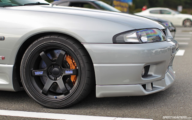
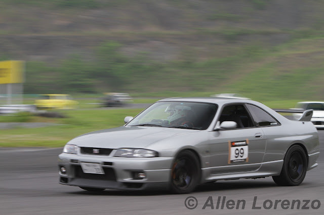
This makes sense, I believe my car is a much better handling car since the addition of various NISMO underbodybracebars, and especially the Nagisa Auto fender brace.

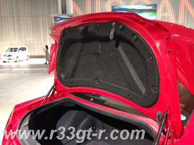
Now the Series 3 has additional bracing in the trunk, but that is in the front of the trunk area - between the struts towers and the rear wall framing where the battery is located.

And this is a result most likely because the BNR34 was being developed during the run of the R33 and in fact the BNR34 test beds were modified R33s. So likely, these braces were an improvement that was discovered during the BNR34 development, and incorporated into the later R33s.

There was one improvement that isn't that well advertised or known, and that is the brace bar in the trunk of the R34.  Not sure why this didn't make it into later R33s, as it is an easy piece to add, however this brace bar concept DID make it into certain models of the S15 Silvia.

So when I began my search for a used piece, I was able to find one in decent shape off of an S15. I had also read on Minkara of anotherR33 GT-R owner (and also a few ECR33and evenER34 owners) who had installed an S15 trunk brace bar without issue, so rather than searching for a BNR34 one, I picked up one of the more easily available S15 ones.

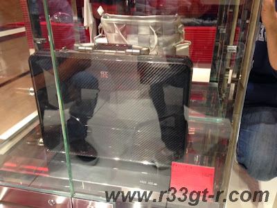
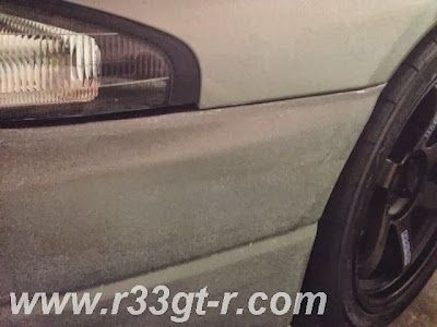
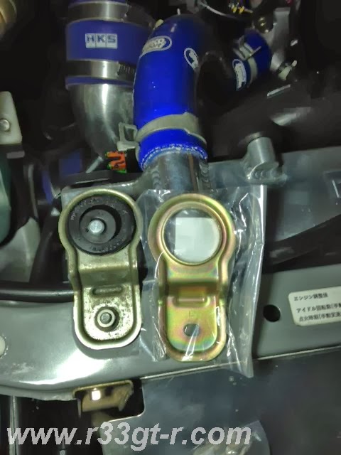
When it arrived, it was in good shape, with some scratches, presumably caused by items in the trunk!

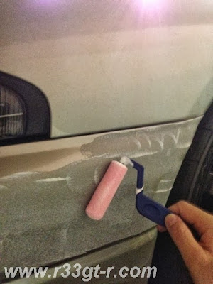
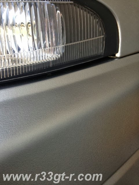
But as I had some leftover KR4 silver paint from my fluidic nozzle project, I used that and sprayed the entire bar to get it as nice looking as possible. Turned out ok, I think:


I let Ninomiya-san of Be Ambitious take care of the install while I left the car with him in order to install the R34 V-spec rear diffuser. It turns out that there are already holes pre-drilled in the trunk in the right place (under some rubber caps), however what needs to be taken care of is to have something fill the gap between the floor and the bumper reinforcement, which also has holes pre-drilled. (Apologies but since I did not do the install I don't know what size bolts...). For my car, Ninomiya-san had some billet anodized aluminum spacers custom made (not cheap), but it is obviously more solid than what people usually do, which is to stack washers one on top of each other to fill the gap. And getting these spacers made took over a week and hence the delay in getting my car back to me (I thought the diffuser and trunk bar install would take a day or two, but it ended up taking a week).

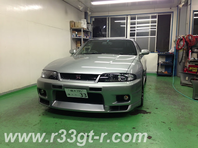
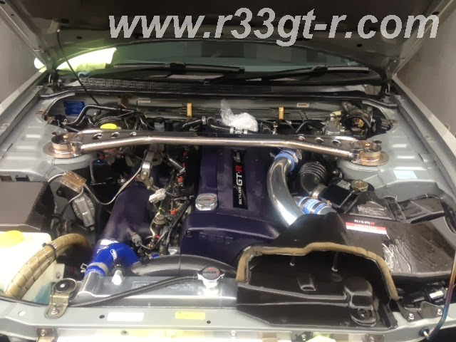
Anyway here is how it looks now, installed.

And here is close-up of one side, bolted in:

Now what about the result? Did it change the car? In a word, "yes!" Definitely!  On my way home after picking up the car, it's only a few kilometers, but immediately the car felt "shorter" - I know that sounds odd but that is the best way to describe it.

Later, I took a 2 hour drive into Tokyo, and discovered that, in addition to the car feeling shorter, the suspension seems much stiffer now. What was before a firm but pleasant ride is now on the verge of being a bit too harsh!  So unless this is a placebo effect, I guess my senses are telling me that, before the trunk flexed and allowed the dampers to feel softer - now as the trunk area is more solid, the dampers don't have as much "give"... at least that's my theory.

Any thoughts, my friends? Am I imagining things? I think I am going to continue making the body as rigid as possible without the use of a roll cage, until the car feels like it's carved out of one solid block of steel. I will look into spot welding, but have heard that rusting can be an issue, so I may just have to see what else is out there that is bolt-on.

Glove Box and Center Console Clean-Up!

$
0
0
One more post before my final diffuser post...

So here is something I've been meaning to do for a long time.  A few months after I got my GT-R, thanks to the UK GTROC forum, I was introduced to a product made by a forum member which was marketed as an alternative to the expensive (or discontinued) torque split controllers by GRID, FIELD (E-TS Linear)  or Do-Luck (D-ETS-M).  But it turned out to be a waste of money, I should have stuck with the tried and true.

Upon installation, I found that not only did certain dash warning lights stay on initially (4WD and ABS, if I recall correctly) and even when I got that resolved somehow (I think I had to reset all ECUs by unplugging the battery, etc.) then I could never tell if the unit was working, even on the track. So it was just a matter of time before I unplugged it.   However, the hole I drilled in the center console to pass the leads through, was too small to pass the harness (I had soldered on connectors for quick release, etc.) so I just left the device in the console box, taking up space. Like so:
Note the hole for the wiring that I drilled
This is how I just left the wires underneath the console, unplugged and unused.
On the other hand, when I first got my car, I had a Navi installed, and one of the options I got at the same time was an ETC reader for electronic toll collection on Japanese expressways. However the shop had installed this in the glove box, which, in addition to the boost controller and later an iPod docking cable, meant for a very crowded glovebox - essentially unusable.

So nothing fit, but I didn't really care, until I bought this beautiful, limited edition, leather "shaken" case from what Nissan called "The Nissan Collection"... designed to fit in the glovebox. But because it didn't fit in the glovebox, I had kept it on the rear seat, which meant it ended up on the floor... not good.
Limited Edition, "Nissan Collection" item.

In addition to the shaken and insurance papers, fits the owner's log and manual neatly
Hence I decided to relocate the ETC reader device from the glovebox to the center console. First, I had to remove the center surround to access the stereo head unit, as well unscrew the HVAC and head unit to access these wires in the glove box which connected to the ETC device.


These wires lead to an area behind the head unit, hence:

And then I was able to reroute the wires to end up underneath the center console box.  Meanwhile, I had "snip" taken out the Skylab device:
Anybody want this? Just pay for shipping and it's yours!
 And then I used a drill and a very sharp knife to create a small space for the ETC wires to pass through:
Not m best work, but since it's usually out of sight, out of mind...
This allowed the ETC device to fit in nicely - even though it appears to be taller than the box, the cover has an indent which means no problems in closing the lid securely - and no problems removing the credit card sized ETC card when necessary, either. And use of double stick cushion tape means this is as secure as can be.

Check out all that space there in front - perfect for some secret unseen switches?

Now the glovebox has more than enough space for the Shaken case to fit.
I'll keep the iPod/iPhone connectivity for now...
In conclusion - while storage space is limited, I now have use of the glovebox. And, given the space still available in the center console, this means any other devices I get - can be located there too. And yes, already have some things in mind.... stay tuned!

BNR34 Rear Diffuser Project, Part 5: Done!

$
0
0
While taking photos of the various pieces that had to be fitted to make the diffuser fit, I realized from the following photo, the rust on the leading metal edge of the diffuser really bothered me.

That, and I also realized that I was simply ignoring another problem, the rust on the inside fin mounts:

So off to the hardware store I went, searching for the Japanese equivalent of Rust-Oleum StopsRust, the paint that you spray on and which slows down the progression of rust (it was too much work to actually strip down all the rust and then respray). I couldn’t find a spray product, but did find something in a can that’s used for black iron fences, etc.


So, I took off the diffuser, and painted all rusted surfaces with this anti-rust paint in the hope that this would at least slow down the spread of the rust that’s already there. If of course it’s too late, well at least I have the stainless brackets and other parts from the RB Motorsports kit that can probably be used in their place.
Looks much better, right?
And, since I had the diffuser off, I decided to see if I could do one more mod.  I remember reading in GTR Magazine about a shop that installed a red F1 style rear LED in the center bracket, and found two examples on Minkara.  (Here's the other).

But, I’m not about to spend 34,000 yen (plus that was a limited edition run of 10 plus units) on this! So I searched on Rakuten and first found this:
Not bad at 900 yen, but the reviews were mostly all bad....
But given that the dimensions I could work with were:  about 6cm for the space between the body of the car and the diffuser, and about 3cm between the leading edge of the diffuser and the bumper, I found instead a rectangular one with better dimensions: 


Once ordered it quickly arrived - and though I'm sure it probably costs less than $5 in the US (and even less than that in China), unfortunately it was a bit more than that here...

So as you can see it had this clip attached to it. Initially I was not going to use this clip, but then decided that, instead of making my own brackets, it might be better to figure out a way to attach it using this clip – either to the car body or to the diffuser itself.


After some thought, I realized that to attach this LED to the car body would require new holes to be drilled, or the diffuser stays would have to be modifed.  It would probably be easier to attach to the LED light to the diffuser itself, so that's what I decided to do.

I found a stainless steel (so it wouldn't rust) bracket with holes, which bolted on nicely to the end bolts of the rear-most bolts of the two inside fins (which are spaced apart exactly 46 cm!) on the inside top surface of the diffuser (you can also see the formerly rusted inside fin mounts now painted black here too):

Then, using the clip that came with the LED light, I was able to test fit it by slipping it (temporarily) on like this:

I was envisioning I would be able to attach it all so it would be like this:


But I then realized that I had to do something to prevent the LED lamp and its clip from slipping off the stainless bracket - so I decided to use a "V" shaped rubber piece with adhesive on both inside surfaces between which I sandwiched the stainless bracket.  The two bolts shown here were then used to center the LED clip on the stainless bracket:  

So it ended up looking like this:

And then to prevent the whole contraption from slipping around and thus possibly falling off, used some silicon adhesive on the side that would contact the diffuser:

After I bolted this whole contraption onto the diffuser (again using the two rear-most bolts of the inside fins), I temporarily re-attached the diffuser to see how it would fit.
Looks pretty good, huh!
Now all that was left was to wire it up to the lights. This I'll cover in a future post, because it took some time to get right.   In any case - finally - here is the finished result, in day light! Comments, critiques, and questions most welcomed!


HID Rear Fog Lamp, NOT a Good Idea

$
0
0
So I recently outfitted the car with an HID back up bulb.  And, found out when doing this mod that, in fact the regular incandescent bulb was BRIGHTER than the LED bulb that had replaced it, which I then replaced with the HID bulb. My conclusion at the time was that the LED bulb was whiter or bluer than the yellowish incandescent bulb, but NOT brighter on the Lumens scale.  The HID bulb was whiter/bluer AND brighter than the LED bulb, so I decided to go forward with the install of the HID bulb.

At the time I had also compared the standard incandescent bulb and the LED bulb for the rear fog light - but it was obvious that the incandescent bulb resulted in a brighter, redder, light. Hence I kept the incandescent bulb in place.

But, while working on final rear diffuser mod, I decided to see what would happen if I took the next logical step of installing an HID bulb in place of the incandescent bulb for the rear fog lamp.  Here is the result.

Incandescent Bulb

HID Bulb
So again the regular incandescent bulb seems to produce the most light for a red lens, as used in the rear fog lamp.  I have to conclude that, despite the HID being "white" versus the yellow of the incandescent, either a yellow light produces more usable, visible light and/or for a RED lens, a whiter light behind a red lens does not always produce the brightest possible light. Or, perhaps an HID is directional and so works best if used in conjunction with a mirror lens surface that focuses the light in a proper way (like the headlights).

So the next step will be, researching the brightest possible incandescent bulbs! Stay tuned....

Wiring up the DIY Rear Diffuser LED

$
0
0

Continuing from my last diffuser post- the final step in the BNR34 rear diffuser project was to wire up the LED. So this is how I did it:

The LED unit itself has 3 leads coming out of it, labeled+- and brake.  The unit was described as having aflashing brake lamp a la F1 style, and my 12 volt tester confirmed this was the case.

In any case, the first step was to ensure that, should I have to remove the diffuser in the future, I would be able to disconnect the leads without having to cut any wires. So, I found and ordered 3 lead to 3 lead connectors, which I then soldered onto the ends of the wires coming out of the LED, as well as to 3 wires leading into the body of the car.

It ended up looking like this:
See the white connectors
Next, with the wires being exposed to the elements, I wrapped electrical tape around the leads, and also used some protective heat shrink tubing for the LED leads going all the way into the body.  There is a rubber grommet (which has other wires going through it too - most notably the back-up camera leads) covering a hole just above the license plate frame, so I passed the wiring and the heat shrink through this.

I then removed the rear seats, ran the wiring alongside other wiring, zip-tying strategically, and then routed the wire to underneath the center console.  I soldered on some connectors (one side the wires from the trunk, the other on the wire leads going to the switch), to allow for complete removal of the center console when necessary, and then ran the connecting wiring through the pre-existing hole that I had drilled for the ATTESA controller that never worked right for me. I made sure I used connectors, so if I ever need to remove the console, I don't have to cut any of these wires.


On the trunk side, because the wiring into the car ran on the left side, I opened up the rear left side light cover to access the wiring there.  I then cut two short pieces of wire, and soldered the ends of both to a two lead connector.  On the other end, I soldered one wire onto the lead for the running lamps (there was already two wires soldered together on the factory harness for the two left rear lights, so I simply soldered on top of that, rewrapping in electrical tape), and then used a tap for the other wire, which I connected to the brake light wire.  This two lead connector was then attached to the two lead connector for the two wires coming BACK from the main cabin. So now I had one long connection going from the bulbs to the center console. I used clips throughout, in case in the future I want to remove part of the circuit but keep other parts, with no cutting required.

For the lead coming from the LED unit, I soldered a connector to the ground wire and bolted it to the body. The remaining two wires - one being the positive lead for the running lamps and the other for the brakes - I ended up also soldering leads for connectors, to be mated to the appropriate connector for the wires leading to the main cabin area. So this was the other long connection, going from the LED to the center console.

So, I now had a complete (fairly long) circuit, broken only by a lack of a switch connecting the two leads coming INTO the cabin from the LED unit itself, and the two lead going OUT into the cabin to be wired into the brake light circuit.   Initially I had envisioned have one switch handling the ground wire only and serving as a master on/off switch, but then realized that I wanted independent control of the braking and the running lamp circuits, as the flashing red lamp clearly violates Japans shaken (road-worthiness) laws.Thus I ended up sending 4 wires into the cabin (2 in, 2 out).
Here is the harness I made, open leads (4) to connect to the switch, the clip inserts into its mate underneath the center console
Given the need to be able to quickly toggle the LED on/off from within the cabin itself (i.e. remember this mod likely is illegal on public roads), I spent some time looking for various switches which would work. Initially, I was set to use these tiny switches, with one switch being for LED to come on with the running lights, the other switch being for the LED to be wired into the brake circuit.  

The problem, however, was that I now had the problem of how to affix these switches to the center console.  Do I carve out two holes directly? Or do I have some kind of bracket? Where would I locate them? Should they be visible? Or do I install in a hidden spot?

In the end, I finally decided that something that looked or was, OEM would be my best bet.
I found this on Yahoo Auctions - it is the switch for the OEM Nissan optional foglights,
as our
 red R33 friend Miyuki-san demonstrated
But rather than placing this switch next to the GT-R logo where it is normally placed:

I decided to continue with the stealthy scheme and install inside the console.  So this required some cutting of the center console for the switch to fit.
The center console, as seen from below - I had to use a drill and drill several holes
as the angle was wrong for the Dremel!
And then use a very sharp razor knife to make nice and clean
Then, I discovered that while the switch fit perfectly, the switch itself was too tall, meaning I had to cut off some of the bottom of the switch, and also bend the leads on the wires so they could connect to the switch with minimal amount of wiring sticking out of the bottom vertically, where it was bumping into the G-sensor.

Used the Dremel here!

Note how the leads are bent 90 degrees
The end result, however, looks fantastic, is solidly mounted and is hidden.
Actually it looks here like it's lifting up a bit, but in reality the switch is flush
with the floor of the console box
Anyway, it all works perfectly in the end - here is a video showing the LED lamp in action: First, just the running lamps, then turning the switch on to get the running lamps plus the LED, then the brakes with the LED (see how it flashes), then release the brakes, then turn off the LED.


So now all that's left to do is see how the diffuser performs at speed...

Speedhunting: Izu Skyline Drive with Friends

$
0
0

This year, I have been too busy to take my car out on a proper drive. Lots of minor tinkering, yes, but not a chance to really enjoy the car for what it’s built for.

This changed when my friend Dino proposed a short drive trip up to the Izu Skyline road near Hakone, ostensibly to try out his new tire and wheel combination, but we both knew the real reason was for all involved to de-stress from our daily lives.

Here is the link to his fantastic as usual Speedhunters post. He does a better job than I could of explaining the route we took and the scenery along the way, so I won’t bother to describe the trip (please read his post) and further I have taken the liberty to borrow these photos from his post:


So hard to take a decent photo of these brakes and the car, but I think Dino did it! Except the car looks grey...
As Dino mentioned in his post, the three of us, Thomas in his Midnight Purple BCNR33, Dino in his Bayside Blue BNR34, and myself, first met up at the Ebina Service Area off the Tomei.

Yes, Dino was late...
Hey look, those non-functional brake scoops actually work... kind of...
In addition, we met up with our friend Matt (BNR32 owner) who was on vacation in Japan and kindly agreed to meet us up there in his rented orange Z34 Fairlady. You can see it in one of Dino’s photos.

I also took some photos, but they were nothing special.  Matt had a decent camera with him and was kind enough to share his wonderful photos for inclusion on this blog. Here they are, and thank you again Matt!

Here is the entrance to the Toyo Tires Turnpike, which then leads up to the Izu Skyline Road!
At the top of the Turnpike, Matt was already waiting for us... here I am explaining to Dino that
Matt beat us up to the top...
From another angle...
Close up of my car while in the three car formation at the top of the Toyo Tires Turnpike. Yes, Thomas was driving in his beach sandals...
After the Tsubaki-line run, I kept going... into the town of Yugawara.  Here I am after I called the boys and re-met up with them where they were waiting for me...(Dino had to cool off his brakes anyway...)

Fantastic picture Matt! The lighting is sublime, I love how clean the car looks!
At the parking lot on the Izu Skyline. Just like the photos in Dino's Speedhunters post.
And here we are cooling the cars off... getting ready for Dino's mini photo-shoot.
So there you go... and for those of you who know me, yes, I was running a new "mod" which I will talk about in my next post. Stay tuned!

Sacrilege??

$
0
0
Over a year ago, when I embarked on the sound deadening project I had bought several spray cans of this:


Looking at reviews online in Japan, this product (the "Beat-Sonic Noise Reducer") was generally acknowledged as the best, not only in sound dampening ability, but also as a general undercoating (to prevent rust) in cars.

Luckily, as they don’t use salt on the roads in the winter, and also because I frequently wash my car, there are very, very few spots of rust on my car.  The few spots that I have spotted were surface rust on the car when I first bought it (mostly easily removed), and I haven’t seen any new spots since.  So really, there really is no need to apply an undercoating, so long as the car is in Japan and relatively well maintained.

Here is the worst of the rust.
I was hesitant to spray this on for a few reasons – one obviously is weight, but the other was, would this material be removable in case there was a spot of rust that got out of hand and that panel had to be repaired?  Again, is it really necessary for me to do so?  Sacrilege to unnecessarily paint my car??

In any case, I thought I reached a happy compromise by deciding that I was going to spray ONLY on the inside of the fenderwells, behind the wheels, where I suspect most of the road noise was getting through (because the floor had been lined with the sound deadening material already, on the inside) AND because I planned to spray the stuff ONLY on the plastic fender liners.

So, I jacked up the car, took the wheels off, then liberally sprayed on some Simple Green to break down any dirt there.

And yes, I also took the opportunity to clean the wheels, especially on the insides where there was some brake dust.
Hard to clean as those calipers leave only a few millimeters of space


Oh, and yes, what a great opportunity to clean the R35 brembo calipers!
This dirt had been bothering me for a long , long time...

Ahhhhhh....
I then used my trusty Vapamore steam machine to REALLY get things clean.

Before:

After (and after I started wrapping with newspaper):

I then covered up all the important components with newspaper, and began to spray on the undercoating.  But then realized that, I might as well go for the metal too (which, I believe, already has a CLEAR looking (but now yellowish) factory undercoat in some places)

So here is how it looked after spraying on the undercoating.  In addition to rust protection and sound deadening, I realized then of another advantage – of making the inside of the wheelwells look dark, thus enhancing how the wheels look.


And the result? Nice and CLEAN and BLACK....lol.  Oh, and also as the pitted plastic liners are now covered with the deadening, hopefully they will be easy to keep clean now.

As to whether the coating had an effect on road noise, in my judgment, "yes" but only slightly. Then again with the Tomei Expreme exhaust uncorked, it was a bit hard to "hear" the difference over the exhaust note, but during the Izu Skyline run, it just seemed that under some circumstances, the car DID seem to have a bit less road noise...

The background is all black....

A Bit of a Nip and Tuck....but Two Cool Photos...

$
0
0
Actually, all I had initially wanted to do was for the front lip spoiler, which had gotten scraped in a pay parking lot,  to be resprayed.  But then, I decided to stretch my budget and get the front bumper resprayed as well, getting all those rock chips and scratches taken care of.

Here is how the car looked when I picked her up on Sunday evening from my neighborhood shop, RAPT:
How I wish I had my DSLR with me that night...
And it turns out that, Kabe-san at RAPT has special spotlights that light up when the main overhead lamps are extinguished. To the naked eye, the silver seemed to glow, like it was alive. Obviously this iPhone photo doesn't do it justice, but I think you know what I mean.
Hmm. This might be a decent place for a night shoot.

We also discussed future "clean up" type work going forward....

Can There Be Too Much Body Rigidity?

$
0
0
(Or, what I was actually doing at Do-Luck on my day off this past Monday)

So as I continue to bring my car up to more modern standards, one area where I have spent time, money, and effort recently, as readers have noticed, is in the area of improving body rigidity.

So far, I've attempted to add body rigidity to the following areas:
Rear trunk area (cross-wise):  S15 Trunk bar
Front fenders (longitudinal): Nagisa Gacchiri support
Front underfloor + steering rack (cross-wise), replaces standard front cross bar: NISMO Front Underfloor Reinforcing Bar
Center underfloor + rear suspension (cross-wise), replaces standard center cross bar: NISMO Center Underfloor Reinforcing Bar
The chassis and subframe: Spoon Sports "Rigid Collars"
Not exactly a “stiffening” part, but something that cancels out the excess vibrations caused by stiffening: NISMO Performance Dampers

This past Monday, I added one more - theDo-Luck Floor Support Bar!
Courtesy of Do-Luck RS webpage; Floor Bars (aluminum) shown on demo R34 GTR
While I thought that my body rigidity work was finished after I got thetrunk bar installed, in the back of my mind, I had my doubts - was I doing the right thing? Were these reinforcement parts working in the additive sense - was having more rigidity everywhere, better? Or was I risking unbalancing the car?  After all, during my research into the differences between the R33 and R34 GT-R, there was some extra welding done in the C-pilllar, and the trunk bar, but nothing about fender and underfloor bracing...

And as you recall from my results after the trunk bar installation, the ride quality got much stiffer, in fact on the verge of being too harsh! So did I really want to further stiffen the car?

A while back I had called Ito-san at Do-Luck and asked him this question.  He believed that it would only benefit my car to tighten up the floorpan, that what I had done so far wasn't excessive. So, it was only a matter of time before, when I had a day off, I drove over to Do-Luck to get their Floor Bars installed.

They were waiting for me, so I had them pull my car into the workshop because... 
As you can see it was pretty crowded in there that day.
No way I'm taking responsibility if I accidentally run into something!
I spent most of my time while there talking to Ito-san about his latest product, the DTMII ETS Controller, (I volunteered to translate the manual, so he gave me some inside info as to how it work! I hope to share it here soon...) so did not watch as his staff installed these:

However the concept is ridiculously simple - using lightweight aluminum, oval shaped (in order to prevent excessive underhang) bars that bolt on to the underbody in 3-4 places. Here is an interesting tidbit - he found that some 33s had 4 mounting holes available (like my car) but others only had 3. Hence he ended up standardizing his bars to have 3 mounting holes, as can be seen in the photo above.  However, ALL R34s have 4 holes on the chassis, so the R34 bars all have 4 mounting holes... not sure if it makes a difference but it would have been nice just in case...
Close-up of rear of bar (looking towards front) showing how the NISMO brace fits OVER the Do-Luck one, no problem
Ito-san remarked that as he had developed these bars BEFORE even NISMO released their series of underfloor reinforcing bars - he had never seen the above scene before in person!  I couldn't believe it myself, but it was the first time he himself had seen that these two pieces fit without issue. Turns out that not many of his customers get their pieces installed at his shop, and I guess I was the first R33 with the NISMO pieces to do so...
Here is the front of the bar. You can see how there is a hook that ties it securely to the frame
 (prepped with anti-rust later, of course)
sorry for the blurred shot, but you can see how the bar runs along the chassis 
Anyway, based on my research I don't think there are any more aftermarket add-on parts available to improve body rigidity.  So I think I am done with this type of body rigidity improvement. When I have the time, I’d like to follow up on methods to stiffen the shell by way of either spot welding, or hardening foam (for example in the C-pillars, like the BNR34).

After the work was done, I then took a quick spin toNissan Prince Shinagawa and visited their Motorsports Division to order some additional parts for some upcoming projects I have. You’ll have to check back in order to see exactly what I got….

But more importantly during the drive over, I could DEFINITELY feel that the Floor Support Bars had made a big difference, more than what I had expected. 

First, the harsh ride was gone!  I asked Ito-san about this, and he explained that the trunk bar had solidified the rear body and allowed the rear coilovers to work off of one solid base - so the left and right sides were unified, both front and rear.  However, with the longitudinal Do-Luck bars now installed, all 4 wheels were tied together, allowing the suspension to work off of one large, solid base.  Indeed the car feels more solid, more carved out of one piece. 

Second, the car felt shorter, and more nimble. It might be my imagination, but it seemed that there was a bit less "lag time" when making high speed lane changes, for example. Obviously I can't quantify it by saying it took 0.00000005 seconds less (or whatever) to respond, but there is definitely a difference in how the car feels. I recall this is the same feeling I had when I first had the Nagisa fender braces installed.  So perhaps front/rear rigidity improvements can be had with longitudinal bracing?

Sadly I got used to this improvement in feel after about 10 minutes of driving...and now I'm wondering if it makes sense to get the car spot welded where I can! In any case I'm actually looking forward to going for a spin soon...

Clear Film Paint Protection... Sort Of

$
0
0
So having gotten my car refreshed (i.e. front bumper repainted) recently, this time I'm determined to make sure that the newly painted parts remain as clean and pristine as possible.

One solution, of course, is to never drive the car, but this is not practical.

After doing some research, I believe there are four solutions:

1) Do nothing. That is, just have the bumper and front lip spoiler repainted every other year or so, whenever the damage becomes an eyesore.

2) Application of 3M Scotchguard Paint Protection clear film.
This would actually be the best solution...
The drawbacks are, however, expense (I have found very few shops in Japan that do this film application which means very expensive), and in this particular situation, the inability to cover all the painted areas, given all the openings, scoops and complex shapes on the front bumper and the lip spoiler.

I actually tried doing this myself before with limited success (the headlights came out great):
Using tracing paper to create patterns for the 3M film
During application: before squeegeeing the liquid out
However even though I managed to wrap the front lip spoiler, it never looked right as the cutouts for the front brake ducts were sloppy, and then when I scraped the lip spoiler, the impact left the film scarred and scraped up too. So when the lip spoiler was repainted, it was removed of course.

3) Application of 3M Paint Defender Spray Film (I have no experience with this, but hope to try it out in the near future)
Check back as I experiment with this in the near future!
This seems very promising - almost the quality of the 3M Scotchguard film, but in a spray format? The internet reviews are mixed...

4) Application of Road Warrior Plus
This is the basic kit - the liquid in a quart bottle, plus application tools.
This is what I ended up getting.  Basically, this is a liquid that you paint onto those car surfaces that you want to protect, and when dry it is supposed to serve the same purpose as the clear film.  That is, provide impact protection from stuff on the road. Of course, given its relatively thin (when dry) nature it is marketed more as a temporary solution for track days (apply, race, then peel off) and long distance driving where road debris can be expected to hit at high speed.

Ingenious in concept, but a) is it really that easy, b) does it look ok when dry, and c) does it work?


So I got to work. First, as many reviewers remarked, this stuff DOES smell, and have the same consistency, as Elmer's glue.
Ok this roller is cute, but will it do the job?
Before pouring the RWP into the tray, I wiped down the front bumper and lip spoiler. Also, I decided to do my left side mirror as well, more to be able to demonstrate to people who ask.

I seems to go on very thick.....
But after you start spreading it out with the roller....
You end up with a very thin coat of spackled Elmer's glue-like stuff
This whole process took only about 30 minutes, and I did two coats (dried the first layer with a hair dryer), at night, when it was about 18 degree C outside (so maybe a bit more inside the garage?)

Here is what it looks like, in daylight after it is dry.
Can't really tell from this distance...
s
But close up, you can see the orange peel effect quite clearly
Close up, it looks like really bad orange peel, but it feels like plastic, not paint. There were some areas where I had forgotten to smooth out the liquid well, which resulted in some clumping but in the end they dried clear too.  As you can see from far away it doesn't look too bad, I think.

I had actually done this right before my visit to Do-Luck and Nissan Prince on the 30th, and both Ito-san and Koyama-san thought I had subjected my car to the worst ever repaint...before I explained that it was a roller applied film...

Now to test it...seems almost too good to be true if it can actually provide significant protection. Yes I've driven to Shinagawaand back, but I think we need a longer trip. Stay tuned....

Engine Bay Detailing and Parts Replacement

$
0
0
Well as most of you know I DO like to keep my car clean.  And this means not just the exterior and interior, but also places that are not as obvious, such as the wheel wheels, inside body panels, etc. But I realized that lately, I had been neglecting one very obvious area: the engine bay.

So, the morning of the Izu Skyline drive, I took about an hour and used some Simple Green and some elbow grease to clean the engine bay (also, I figured that Dino would probably take a photo of the engine bay… I was right!!)

Using some plastic sheets, I protected the sensitive parts from water, and then proceeded to spray down the engine bay.  Once dry, I then sprayed on some CD2 protectant that I have had forever (I think I bought it back in 2007?!!), and was sitting in my collection of detailing tools.


 Freshly sprayed, it looked like this:
You can see the plastic bag protecting the Okada Plasma wiring, as well as the not yet dry CD2 spray

So if you look closely, there are a couple things that bothered me.
1) The fusebox cover: I had a vendor lay wet carbon over the original fusebox cover. And it came out terrible.  You can see in the photo above, it looks ok from a distance... but not up close (so we borrowed Thomas' for the Speedhunters photo)
2) The plastic clips on the steel brake lines, along the firewall.  Actually Midori Seibi's Uchinaga-san (the son, R33 owner as well) had pointed that outduring my visit to Midori Seibi back in January.
3) The radiator stay. Mine is rusted and has dirt built-up. One is visible, the other is hidden under the air intake snorkel.

So I had to get replacements for this. And hence my trip to Nissan Shinagawa the other day, to pick up a few parts:

1) New fuse box cover
2) White Plastic clips (3)
3) Radiator stay
4) and small clips (2)

The two clips, I will use in a future blog entry.
Otherwise, as fitted these new parts did help to freshen up the engine bay (apologies I took these photos with my iPhone at night...):
Old (borrowed from Thomas again) and new Fuse Box Covers

Hmm. That new one looks weird.
 I wonder if I can get the old one chromed or something...


Comparing the plastic clips that hold the brake lines in place!
The old ones had turned yellow (and 2 of 3 had cracked) due to the heat of the engine!
And here it is installed - I have one more thing I want to do so will have a better picture when I do that mod, but until then, this photo will have to do.


"The R33 is leaner... and more GT looking..."

$
0
0
I was pleasantly surprised to hear the readers of /DRIVE agree that the Skyline GT-R was one of the three Japanese cars to have right now.... (and even more that the hosts agreed the 33 was leaner and more GT looking than the 34...)

Unfortunately, not much more about the Skylines...other than, it's one of their "hero cars" which are essentially unobtainable in the USA.

Hence, most of the time is spent talking about other cars.... but a few I wouldn't mind having, actually!

Enjoy!


Here is the link:
http://drive.jalopnik.com/what-three-japanese-sports-cars-should-you-buy-now-1443711691

Lip Spoiler... I'm not giving up...(to prevent scraping)

$
0
0
So while I prefer the look of the OEM Series 3 lip, the drawback is that due to it being 20mm longer than the Series 1/2 lip, it seems to ALWAYS get scraped up.  In fact, this is the reason why original buyers of the Series 3 cars were able to order the Series 1/2 lip, as an option from the factory.

A bit more and I scrape...

See how much shorter the Series 1 car's lip spoiler is!


When in its OEM black ABS plastic form, sometimes the scratches aren't very noticeable because they are on the bottom edge, but once you make the decision to paint the lip, then a scratch can no longer be buffed out, or sanded down like ABS plastic can.

So in my quest to protect the lip spoiler, I am currently experimenting with the Road Warrior Plus paintable clear bra alternative.  So far, so good I think. However there is nothing in place to protect the lip from scrapes, in case I end up pulling into a slightly too steep driveway. I need something that attaches UNDER the front lip spoiler that can sacrifice itself and give tactile and audible warning when it hits something solid, and cause me to stop (also something that doesn't weigh too much or cause drag is important, too!).

Long time readers will recall that in the past I tried long rubber strips (a Nismo aftermarket part), as well as thin aluminum strips for this purpose.  The aluminum worked well initially, but I found that a section would give and break away but other sections would not, creating pieces that would drag on the road, and even end up getting caught up in the wheels. Not good.  The reason being I just could not attach them securely enough.

I've even done a 3M DIN-OC carbon fiber wrap.

When I consulted my engineer friend Andrew Brilliant, his idea was to have a separate frame or section that could absorb the impact without putting stress on the lip spoiler and bumper (like what happened and resulted in my having the bumper and lip spoiler repainted...)   Although his idea was too complicated for a simpleton like me, one thing I did decide to follow up on was having something that was "soft" and could "absorb the impact."

Initially I was thinking of rubberized metal strips that I would bolt on using the screw points of the front diffuser, but that got too complicated. I finally settled on this:

The install was very easy. Less than 2 minutes per screw - that is, I would unscrew the shorter screw that is currently used to hold the diffuser in place on the leading edge of the front lip, then replace with the longer screw threaded though a rubber grommet, to end up with this:


Very simple, right? Hopefully these are the lowest points of the front lip spoiler and will drag or catch first.

So far I've done a 300 km trip that included Sodegaura Forest Raceway for the Skyline Festival 2013, even drove on a dirt road leading to the gravel parking lot, and no problems. Hopefully these will work - not that I want to, but they are cheap to replace if they ever get torn off. I'll let everyone know how and if they work...

Preview: the Do-Luck DTMII

$
0
0
My quest to modernize my car continues...

Trying out "live blogging"... Check back later tonight as I report on the install and my driving impressions of Do-Luck's latest electronic wonder!

Do-Luck's DTM II, Part 1 - The Installation

$
0
0
Courtesy of the Do-Luck Website: http://www.do-luck.co.jp/product/1452
In perhaps another world's first, I was given the honor of being one of the first R33 GT-Rs on the road to be fitted with the DTM II - Do-Luck's even more advanced G-sensor - now with throttle position input and being driver and tuner programmable as well.  (I am certainly the first to do a full write up in English, so I hope I get this all correct!)

To review, the Do-Luck digital G-sensor devices (both the Digital G-Sensor model and the Tarzan GBOX) replace only the OEM G-sensor, located under the center console in the RB26 GT-Rs.
The Do-Luck Digital G-Sensor
The TARZAN GBOX
The DTM II adds not only 7 different settings, (1 of which is user programmable and 2 others which are programmable by select tuners; and the user also is able to modify all the maps simultaneously) but also an organic EL display unit with 5 input keys and compact enough to be mounted almost anywhere in the car.  Installation is straightforward, but since a picture is worth a thousand words:

The very plain box the DTM II comes in
The contents of the box
 The first step is to remove the shift knob, shift knob surround, and ashtray, and then undo the screws holding in the center console, in order to access the G-sensor installation location.  In my case, in my effort to keep my car looking as stock as possible, I chose to install the EL display unit inside the console box (and thus chose to give up the ability to be able to read the real time G readings displayed by the unit).

Fits very well indeed.

Of course this means having to drill a hole for the wiring...
Once the console box is removed, step back and review the scene: In my case, as I had previously installed Do-Luck's Digital G-Sensor, the gold OEM analog box was no longer there.

The Red Arrow on the Digital G Sensor shows the direction it should be installed

A closer look
 Remove the old G-sensor. With my car, installation was easier than usual because I had already removed the OEM G sensor. (click on this link for my blog post showing how to).

Removing the Digital G-Sensor
And here is how the DTM II looks, installed
So slightly larger than the Digital G Sensor
 The next step is to wire in the throttle sensor leads. The instruction manual simply said to "splice in" but when I asked Ito-san about this, he clarified that you cut a particular wire coming out of the ECU loom, and then one wire from the DTM II is connected to one cut side, and the other wire to the other cut side.


This is the wire you will have to hunt down

Once that's done, all you have to do is thread the lead under the carpet so it ends up under the main unit. 
So this lead connects to the DTM II main box...
Like so.
Wait? What's this? Two EXTRA leads? 
 That's right. Two outputs. There are three input/output leads, one of which connects to the lead coming from the throttle position. The others are labelled "OPT" and "LOG." The "OPT" one, Ito-san tells me, will soon allow control of the A-LSD (active LSD) found in the V-Spec models (he's working on how it can be done).  The "LOG" lead is for those who like to datalog what is going on in the car.  The unit produces variable voltage according to the front/back and left/right G-forces, and so if you can record that, then you can log this data.


Install finished! Quite easy. No messing around with anything that will get your hands dirty (i.e. perfect for me).  In my next posts, I will go into HOW the DTM II works, how it can be programmed and other details NOT mentioned in the install manual (that I've seen) and yes, my driving impressions (in a word, AWESOME).

Do-Luck's DTM-II, Part 2 - Initial Set-Up and the Settings, Explained

$
0
0
Once installed, the first thing you will need to do is ensure the DTM-II unit "learns" the voltage outputs for closed and open throttle positions on your particular car.

Here is a video clip where Ito-san and I demonstrate how this is done.


This shows that in my car, the voltage ranged from 0.4V at close to 4.1V at full open throttle. This is consistent with what's to be expected, as shown here:


Ok so now we're ready to roll... except you'll need to figure out which setting you want!

There are 7 settings for the DTM II: 4 in "G" mode (displayed as G1, G2, G3, and G4), and 3 in "ARX" mode (displayed as A1, A2, and A3).

Here is a video I shot (at night, sorry it's blurry - the actual device is super crisp and clear) that shows how to switch between the various settings.


Before I describe each of these settings, we first need to review what the DTM II device is doing. Recall that the ATTESA ECU bases its decision making on various inputs, 3 of which are, the car's longitudinal and lateral G forces (from the onboard G-sensor), and throttle position.

Here is a diagram showing the ATTESA map in 3D, showing just how G forces affect ATTESA output. The right axis is lateral acceleration, the left axis is longitudinal acceleration, and the vertical is amount of power going to front wheels.

Taken from the 1997 R33 GT-R catalog
The impetus of Do-Luck to develop its original Digital G-sensor was that due to age, the OEM G-sensors, which are analog devices (basically a pendulum in oil), were degrading to the point where the signals being sent to the ATTESA computer were inconsistent, slow, weak or non-existent, thus preventing the ATTESA from performing as it should.  And an OEM replacement cost somewhere around 130,000 yen and were still analog.  Digital G sensors are now commonplace (most smartphones have them), are inexpensive, ultra accurate, and fast. So it was only natural that the Digital G-sensor was developed.

Both this Digital G-sensor and the Tarzan G-Box, however, do not simply send back the actual raw G force data to the ATTESA ECU.  Both devices actually modify the signal being sent by multiplying the actual raw G reading by a pre-set variable (or set of variables, in the case of the Tarzan G-Box), which, as can be seen from the map above, means that the ATTESA is engaging faster than before because it believes that the car is experiencing higher Gs than it really is. As an example, if the car is actually experiencing an acceleration of 0.3Gs, but the Digital G-Sensor multiplies that number by a pre-set number, say 1.5, so the ATTESA thinks the car is accelerating at 0.3x1.5=0.45Gs.

In "G" mode, the DTM II is acting as a standalone G-sensor.  Specifically, in G1 mode, the DTM-II unit is outputting the same modified G signals as the Do-Luck Digital G-Sensor; in G2 mode, the unit is outputting the same modified G signals as the Tarzan G-BOX; however in G3 mode, the unit is outputting what the OEM unit would have put out when new (i.e., a "pure" unadulterated G signal).

G4 mode is user programmable - that is, the user can choose by what percentage each of the 4 (front, rear, left, right) G forces should be multiplied by, as sent to the ATTESA ECU. The user can choose an amplification between 0% to 200% for front, left and right G forces, but for the rear G force (i.e. braking), the amplification range is between 100% and 115%.

Here is a video where I demonstrate the G4 mode:


So what is ARX mode? Remember with the G mode settings, the raw G-force signal was amplified by a set variable.  In ARX mode, the throttle position comes into play along with the G-forces (however there must still be enough G-forces first, as throttle position alone won't activate ATTESA).  Further, unlike in the G modes where the raw G-force signal is essentially only "multiplied" by a set variable, in the ARX modes both the throttle signals and G-force signals are outputted according to a unique "map" (still based on the original ATTESA ECU map).  Ito-san explained that, rather than a linear output (where all the incoming data is mutliplied by the same variable), in ARX mode each data point is specifically associated with a specifically amplified (or de-amplified) data point which is then sent to the ATTESA ECU.

Ito-san calls A1 mode the "street" mode, and the A2 mode the "circuit" mode.  A3 mode is again a "pure" signal mode for both G forces and throttle position.

Speaking of throttle position, the user can also adjust the throttle position signal being sent to the ATTESA unit, as I show in this next video clip.


Note that I was getting tired and lost my train of thought at about the 2 minute mark, and mistakenly said that at 100%, I would get the "maximum of the ATTESA working to pull me out of the curve." Note this is only true if there are G forces in play as well, as noted earlier.

Also during the video at around the 3 minute mark, I referred to the Optional Map Edit, which refers to one of the two leads which the DTM II has.  Originally, the OPT lead (as shown below) was designed to hook up to the AYC in the Lancer Evolution cars (this unit works with them as well); however as I mentioned in my previous post Ito-san is working on using this to control the Active  LSD found in V-Spec 33 and 34 GT-Rs.

So that's pretty much it for now. I apologize if I left anything out or was unclear.

Finally, in response to a few questions that I have already gotten:
1) No, this unit will NOT allow you to switch to a pure rear wheel drive (FR) car.  Remember in 33s and 34s, there is always some power going to the front, so the only way to get around that is to essentially have a separate switch that cuts power to the ATTESA ECU. (but then you'll get warning lamps). Although I wonder what would happen if you set the front G force setting to "0" in G4 mode...(theoretically, that would mean no signal gets sent to the ATTESA unit, no? Maybe someone will tinker and find out!)

2) The difference between the DTM-II and something like the below, is that traditional ATTESA controllers only amplify the signal from the G-sensor. The DTM-II has its own G-sensor, and further allows for manipulation of the throttle signal.

3) Is it possible for the user to have another channel to self-program? No, however Ito-san has indicated that select dealers will be given the ability to change the programming found in A3 and G3 modes, giving users even more choices (e.g. a setting specific to a certain circuit?)

4) Is it possible to change the ATTESA "map"? No, because that map is onboard the ATTESA ECU.  However given the ability to send different and amplified G and throttle position inputs, it is possible to use only certain sections of that base map (e.g. the most aggressive portions), or distort the map so that the ATTESA unit's lowest/highest thresholds are raised, lowered or both.

In my next blog post, I'll post my driving impressions, as well as address anything else I left out! Leave a comment or question if you have one, thanks!

Do-Luck's DTM-II, Part 3: Some More Info and preliminary DrivingImpressions

$
0
0
So I had a few minutes today to take the car out for a spin. Unfortunately, most of it was in stop-and-go traffic, so I was unable to fully explore what the DTM-II could do. I plan to take the car out for a spin in the mountains or track soon, after which I promise to provide a full report on the driving experience.

However, I was able to shift between the various settings, G-1, G-2, G-3 and A-1, A-2... and yes there IS  a difference, EVEN in city traffic. There is a marked delay in how quickly the ATTESA sends torque to the front wheels, for the G settings versus the aggressive A settings. Even amongst the G settings, I noticed that G-2 (Tarzan G-box) appeared to react the quickest.  However, it was in A mode where I saw the front torque gauge meter needle shoot up to the max of 50kg...in the other modes I saw the needle go up to 10kg consistently, which Ito-san had told me is about 30% power to the front.

Now, an addendum to my previous posts and the instructions.  While driving I realized that, perhaps hiding this device in the center console may be a waste for those of us who like to have interesting info displayed.  In fact, I am almost tempted to put this up on the right corner of my dash, next to the heads up display (I needed something to read speed above 180kph as I didn't want to change the speedometer).  This is because the device displays peak G forces, front, left, right and rear (and the right side of the two vertical bar chart), AND, on the left side of the two vertical bar chart, the real-time longitudinal Gs (as indicated by the "V") and side Gs (as indicated by the "H"):
Very entertaining to see what kind of Gs you can generate while driving...
So my next task is 1) to take the car on a fast drive, and 2) to play around with the driver programmable settings.  Apologies for the relative lack of information in this post, but schedule permitting I hope to be able to at least do one track day before year's end.

Skyline Festival, Mine's, Nismo and Nissan in One Day! (Part 1)

$
0
0
So let’s take a break from the technical stuff.  This post and the next will be light on words, heavy on pictures...

Recently when my friend Kunal Arneja, (a Skyline R33 GT-R owner himself, and co-owner of theCars Over Everything Facebook page or "COE" as I refer to it) visited Japan from Canada, my schedule just happened to be free his second day in Japan. Naturally, we decided to make it a Nissan Skyline kind of day!

Waiting for Thomas, showing various bits to Kunal
First, I picked up Kunal and my friend Thomas at a Yokohama hotel.  From there we set off under Tokyo Bay using the Aqua-Line to get to Sodegaura Forest Raceway, where they were having the annual Nissan Skyline Festival.  It was my first time going, so I didn’t know what to expect.

When we arrived, I was directed to a huge gravel and dirt parking lot. I thought I bottomed the car out on the bumpy dirt trail leading to it, but luckily no damage at all. The parking lot though, was amazing, with Skylines from all generations, shapes and sizes. As well as other more normal vehicles.
After parking, and making sure no dust was on the paint,
we started wandering about....
Skylines and Nissans from all years...
Of course our eyes were drawn to R33 GT-Rs
Oh lord, a "V-spec II"??
This should have been a warning to us... overdone 33s? But we then started seeing some nice ones:
Kunal and I posing in front of this beautiful blue one
Here's a better shot of the same blue R33, courtesy of COE
 Obviously some other nice 33s in the lot too, such as:
This purple beauty on R34 rims...
I've never seen these kinds of wheels before on a 33!
We found an American guy who owns this Hakosuka, so had to take a look inside...
Kunal and Thomas with an Autech 33 GTR, R31, R34 and Stagea
(never mind the next rows and rows of goodness!)
Lovely Autech 4 Door GT-R... I want one! (Eventually)
A short walk then took us to the asphalted area near the pits, where we spotted some more interesting cars:
IMPUL R33-R (one of only 200  made) - front
IMPUL R33-R - rear


Not only was this ECR33 painted an interesting color...
but it had Z-tune style fenders...!!!
this R31 GTS-R was awesome though
This is a STREET LEGAL REPLICA of the real thing!
Yes, it certainly attracted attention!

Some huge rear over fenders... interesting rear spoiler


And in the tents, you could find Skyline and car related stuff, including rare mincars..
Even K.I.T.T. (Knight Industries Two Thousand) was there...
No Michael Knight to be seen, however
And then we spotted two very interesting and memorable (in a bad way?) cars:
Looks OK, right?
NO!!!! Why these pseudo Ferrari tail lights?
This one, I still have nightmares about:
Note creative use of silver door edge guard to protect lip spoiler...
Oh and also the fender mounted turn indicators
(usually popular with the over 60, Toyota Crown driving crowd...)

I almost fainted when I saw this... excessive stickers are one thing, but look closely...
WHY???? Not just the wiring, which lead to spoiler mounted rear facing LEDs,
but the crystals on the side plates...
The ultimate in car security, I guess....(but with crystal accents)??
We then heard the announcement, they were going to let a few cars drive on the racetrack, so we went to take a look:
A nice lineup...
But already a couple of hours had passed, and so we made an impromptu decision - rather than stay at Sodegaura for the rest of the day, why not let my car stretch its legs some more and visit some other places? And so we left for Mine's, which is probably the least accessible by public transportation of all the Kanto area tuners...

Photos and write up inPart 2!

Skyline Festival, Mine's, Nismo and Nissan in One Day! (Part 2)

$
0
0
So as I mentioned in Part 1, after checking out some cars at the Skyline Festival, we decided to drive to the tuner which blessed my car with a handbuilt RB26DETT, Mine's.  

Not surprisingly, upon arrival we found a customer's white R33 GTR in the parking lot:
Note interesting vented front bumper!
Very clean
Speaking of clean I was parked next to a very clean 34...
I didn't like those wheels too much though...too much hassle to keep clean
This photo got me thinking... do I need to darken the red lens of my diffuser LED?
Obviously for Kunal, this was tuner heaven, and they were even kind enough to show him around (the garage, the engine assembly room, etc.) while Thomas and I asked a bunch of technical questions as well as inquiring into some future products... lol. (something to look forward to on this blog!)
Kunal with Nakayama-san, Chief Mechanic
(and yes the Takumi who built the engine in my car!) at Mine's.
The man has built over 1000 RB26 engines during his career...!!!
 The boys memorialized their visit with this photo:
Thomas trying to act cool, Kunal WAS cool...
And then we were off to our next stop...

The new NISMO Omori Factory, no longer in Omori Tokyo but in Tsuzuki-ku, Yokohama (access map here). Inside, we saw there were several cars displayed, including the original Z-Tune, but also noticed actual cars being worked on behind the glass:
Like this Clubman Sports BNR34

There was also a 400R, but it was slightly out of camera range, darn (and we were not allowed inside).

Of course there was the gift/parts/accessories store selling all sorts of interesting goodies:
Not enough time, not enough money...
But I really enjoyed the nice touches on stuff like:
A NISMO vending machine!
Camshafts being used as door handles to the bathrooms!
And more camshafts in the bathroom!
As we were leaving, we took one more photo outside... I didn't want to do this but the guys insisted, so:
Backing the car in as if it's being driven off the showroom floor!
It was getting late, so then we headed over to nearby Nissan Global HQ in Yokohama to check out what cars were on display as well as do some more shopping at the Nissan Gallery Boutique store.
Kunal found a cool T-shirt...
Nice clock, but why the black caliper? Need gold!
And of course, the $5000 carbon fiber GT-R suitcase...
And check out what we found on the Nissan Gallery floor:
Trunk of an R35 GT-R. And herein lies a clue to a future mod for my car...
We then headed to a nearby restaurant to discuss all things cars while eating all sorts of Japanese food, a good way to finish a LONG, but good day! Thanks to Kunal for understanding my obsession to keep my car clean and parked securely (and for patiently tagging along with me lol), as well as for letting me share some of COE's pictures on this blog!

Photoshoot at Tatsumi PA

$
0
0
Last Monday night, my good friend Dino Dalle Carbonare invited me to join him for a photo shoot. Turns out there is a delegation of German motor photojournalists in town, with world renown Japan based motorjournalist Peter Lyon showing them around! And they wanted to shoot a few nice GT-Rs! 

Anyway - I arrived at the PA at around 2045, and after answering questions about our cars we then got the cars lined up under the direction of the photographers.  Here are a few shots to show what they were doing (apologies for the iPhone night shots):


Turns out this gentleman shoots often for German magazine Auto Motor und Sport! So it will be interesting to see how these turn out. We ALSO drove along the wangan with him hanging out the window of Dino's car and Peter's van taking shots of us "racing" along the Yokohama bay bridge, etc.

When I get wind of the final photos, of course will share here! Thanks again Dino for the invite!
Viewing all 336 articles
Browse latest View live